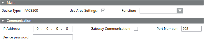
UseArea Settings: Deselect this box to manually set the required parameters. By default, this box is selected, so that configurations are derived from the parent area node.
Function: Select the graphics function to be displayed for the device from the list of available functions.
The fields displayed in the Communicaton expander vary according to the selected device type.
Power Devices
The displayed fields will vary according to the selected device.
IP Address: Specify the IP address of the device for communication. When communicating via a gateway, use the IP address of the higher level. When communicating via Modbus TCP, use the IP address of the device.
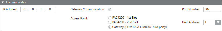
Gateway Communication: Select this check box to activate gateway communication if the device is connected using Modbus RTU via gateway.
Port Number: The default value is 502. NOTE: If a device is connected using the Slot 1 of PAC 4200, use port number as 17002. Similarly if a device is connected using the Slot 2, use 17003.
Access Point: The check box is by default selected setting the Access Point to the Gateway (COM100/COM800/Powercenter 3000/ThirdParty).
Unit Address: Default value is 1. Denotes Modbus address in the Modbus RTU subnet. NOTE: The unit address is reset if there is any change in IP address or Gateway Communication under the Communication expander are changed.
Device Password: Password-protected devices can only be synchronized when you enter the correct password. You can only enter numeric values of 4 digits.
User name: Enter the user name.
PQ Devices
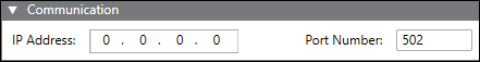
IP Address: Lets you specify the IP address of the device for communication. The value of the IP address has to be between 0.0.0.0 - 255.255.255.255.
Port Number: Port number of the device. The default value is 502. NOTE: If a device is connected using the Slot 1 of PAC 4200, use port number as 17002. Similarly if a device is connected using the Slot 2, use 17003.
Breakers
IP Address: Specify the IP address of the device for communication. When communicating via a gateway, use the IP address of the higher level. When communicating via Modbus TCP, use the IP address of the device.
Gateway Communication: By default, this check box is selected, setting the Access Point to the Gateway (COM100/COM800/Powercenter 3000/ThirdParty).
Port Number: The default value is 502. NOTE: If a device is connected using the Slot 1 of PAC 4200, use port number as 17002. Similarly if a device is connected using the Slot 2, use 17003.
Access Point: The check box is selected by default, setting the Access Point to the Gateway (COM100/COM800/ThirdParty).
Unit Address: The default value is 1. It denotes Modbus address in the Modbus RTU subnet. NOTE: The unit address is reset if there is any change in IP address or Gateway Communication under the Communication expander are changed
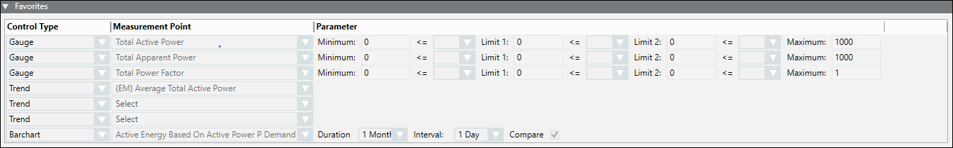
Control Type: (read only) Displays the modes of representation of the parameters configured. You can display the parameters through three gauges, three trends and one bar chart.
Device: Lets you select the devices to be displayed in the Favorites tile in Operating mode with the corresponding representation.
Measurement Point: Lets you select the measurement points to be configured for the corresponding device under the Device column.
Parameter: Lets you set the limits of the gauges and the color for the representing the corresponding measurement point.
Duration: Lets you specify the duration and time interval for which the values have to be recorded. To compare values, select the Compare check box.
The fields displayed in this expander differ according to the selected device.
Device: The device to be configured.
New: Click to add a device.
Delete: Removes the selected device.
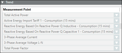
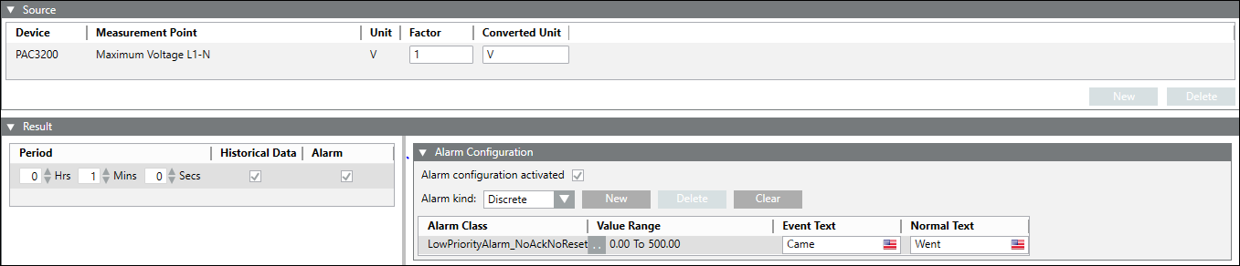
Measurement Point: Select the required measurement point value.
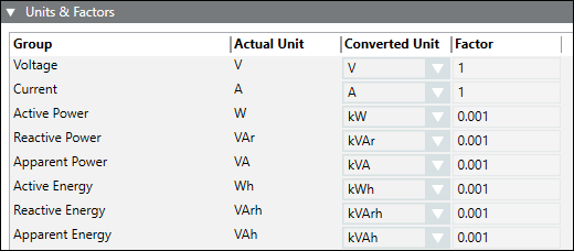
Unit: Displays the unit of the average value data point.
Factor: Enter the desired factor to calculate the average value for the defined unit.
Converted Unit: Enter the unit to which the selected measurement point be converted.
Parameter: Use these assigned parameter values in the formula text field for calculations.
Resultant Unit: Displays the unit of the measurement point after conversion.
Period (Min): Select the time interval for which the energy data is collected.
Historical Data: Select this check box to configure the device using historical data.
Alarm: Select this check box to setup alarm configuration for the device.
Dividend: Allows you to specify the dividend value for KPI calculation.
Divisor: Allows you to specify the divisor, either as a measurement point or as a manual value. If the divisor is not an energy measurement point, the last archived value of the calculation interval at the time of KPI calculation is considered. If an archived value is not available, the instantaneous value of the measurement point at the time of KPI calculation is considered. However, if it is an energy measurement point, the energy consumption for that calculation interval is considered for the KPI calculation.
Measurement Point: Select this option to specify the divisor as a measurement point.
Manual Value: Select this option to specify the divisor as a manual value. If you select Manual Value, you will have to enter a Value and Unit for the KPI calculation. The value of the divisor should always be greater than 0.
Cost Factor: Select this check box, if you want to enter a cost factor for the KPI calculation. You must also specify a currency associated with the cost factor.
Information
NOTE: Use drag and drop function to add Non-Powermanager devices..
The fields displayed in this expander differ according to the selected device.
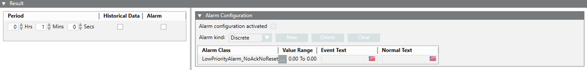
Period: Specify the time period for which the average value is to be calculated for the device.
Historical Data: Select the Historical Data check box if you want to calculate the average value on the basis of historical data.
Alarm: Select the Alarm check box to set up alarm configuration for the device.
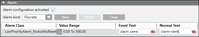
Alarm Configuration: Allows you configure alarms:
Alarm configuration activated: Select this check box to activate the alarm for the corresponding measuring point.
Alarm kind: Allows you to choose the type of alarm to be activated.
New: Allows to add new rows with default alarm class and values.
Delete: Allows you to delete the selected alarm row.
Clear: Allows you to remove all alarm conditions from the table and reset the default alarm class.
Alarm Class: The alarm class to be enabled for an event.
Alarm Class Operator:
For Discrete: .. : In range, !.. : Not in range , || : OR, !|| : NOR
For Continuous: > : Greater than , >= : Greater than or equal to , < : Less than, <= : Less than or equal to
AlarmValue: The value, or range of values, for which an alarm is to be issued.
EventText: The text to display when the alarm is issued.
NormalText: The text to display when the alarm ceases.
UpperHysteresis: The upper range for the alarm value beyond which alarms will be generated.
LowerHysteresis: The lower range for the alarm value below which alarms will be generated.
Formula: Enter the formula and ensure that the formula is syntactically correct. Some examples of syntactically correct formulas are, p1 + p2 + p3, (p1 + p2) / 1000, (p1 || p2) && p3. This is a mandatory field.
Target Value: Enter a target value. The target value acts as a reference value for the KPI. The target value is not used for any KPI calculations but is used in configuring the range associated with the KPI.
Calculation Interval: Select a calculation interval from the drop-down list. Depending on the selected interval, the KPI will be calculated every hour, day, week, month, or year.
Gauge: Select the range of values along with the color code for the corresponding measurement points in the gauge section. The default range is from 0 to 1000. Minimum <=Limit 1 ; Limit 1 <= Limit 2 ; Limit 2 <=Maximum.